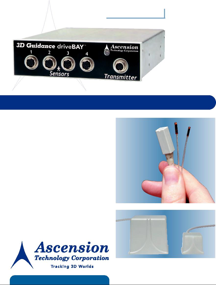
3D Guidance drive BAY
TM
Class 1, Type B Applied Part
Electronics unit tracks
multiple sensors simultaneously
Track Objects with Passive Magnetic DC Technology
Fast, dynamic tracking as many as 420
Interchangeable
updates per second.
sensor sizes for
full six degrees-
Miniaturized passive sensors outputs
of-freedom
tracking
immune to "power-line" noise sources.
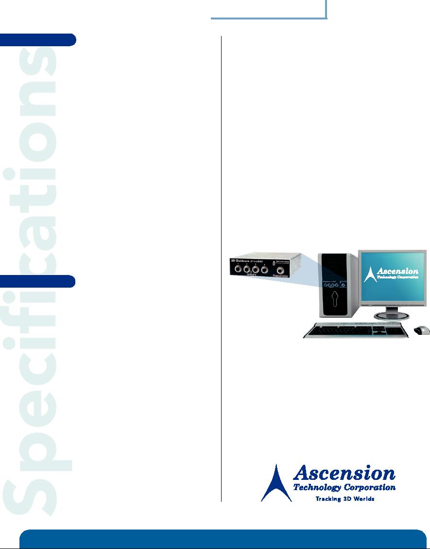
Compact packaging electronics
conveniently fit into drive bay of your PC.
All attitude tracking no inertial drift
or optical interference.
High metal immunity no distortion from
non-magnetic metals.
Magnetic field transmitter options for mid and short-
range tracking
FAST
VERSATILE
AFFORDABLE
3D Guidance drive BAY
FEATURE
Technical
BENEFITS
Metal
tolerant
80% less distortion due to non-magnetic
Sensor Configurations
Model 800 (8.0 mm), Model 180 (2.0 mm)
conductive metals compared to AC
Model 130 (1.5 mm)
magnetic trackers. Outputs unaffected by
Degrees of Freedom
6 (Position and Orientation)
composite materials. Capable of driving
Update Rate
Up to 420 updates/second for each sensor
errors induced by highly conductive
(Default: 240 updates/second)
metals (such as aluminum) to zero by
Translation Range
M O D E L 800 SENSOR
adjusting measurement rate.
· Mid-Range Transmitter: 78 cm (31 inches)
· Short-Range Transmitter: 46 cm (18 inches)
· Better dynamic performance over
Advanced new
MODEL 180 SENSOR
longer ranges.
magnetic technology
· Mid-Range Transmitter: 58 cm (23 inches)
and signal processing
· "Power-line" noise filtered out.
· Short-Range Transmitter: Contact Ascension
for latest test results.
Clear line-of-sight between transmitter
Occlusion and
MODEL 130 SENSOR
and sensor(s) is not required.
drift free
· Mid-Range Transmitter: 46 cm (18 inches)
· Short-Range Transmitter: Contact Ascension
New lightweight coil set can be mounted
Body mountable
for latest test results.
on head or body.
transmitter
Angular Range
All Attitude: ± 180° Azimuth & Roll, ± 90° Elevation
Self-diagnostics and run-time monitoring
Onboard diagnostics
Static Accuracy*
Position: 1.4 mm (0.055 inch) RMS
for improved tracker reliability and safety.
Orientation: 0.5° RMS
*Higher accuracies achievable in smaller tracking
XP/Pro and XP embedded compatible
Software support
volumes.
*Accuracies vary depending on specific
with SDK and sample programs. API with
transmitter-sensor configurations.
expert support facilitates incorporation
Static Resolution
Position: 0.5 mm (0.02 inch) at 30.5 cm
into user applications.
Orientation: 0.1° at 30.5 cm
Outputs
X, Y, Z positional coordinates, orientation angles,
orientation matrix or quaternions
Interface
USB 1.1 and 2.0
Data Format
Binary data records
Communication
Windows API and Drivers
Physical
Electronics Unit
20.0 cm (7.8 inch) x 14.7 cm (5.8 inch) x 4.1 cm (1.6 inch)
Tracker electronics fit
metal box fitting into a 13.3 cm (5.25 inch) PC drive bay
into the drive bay of a
Transmitters
· Mid-Range: 9.6 cm (3.8 inch) cube
PC chassis and uses its
with 3.3 m (10.8 ft) cable
· Short-Range: 6.27 cm (2.5 inch) x 4.6 cm
power. No power
(1.8 inch) x 5.2 cm (2.1 inch) with 3.3 m (10.8 ft) cable
supply required.
Passive Sensors
M O D E L 800 : 8 mm (.31 inch) X 20 mm (0.78 inch)
with 3.3 m (10.8 ft) cable
MODEL 180 : 2 mm (0.07 inch) X 9.7 mm (0.38 inch)
with 2 m (6.6 ft) cable
Regulatory Certifications
MODEL 130 : 1.5 mm (0.05 inch) X 7.7 mm (0.30 inch)
with 2 m (6.6 ft) cable
· Class I Medical Device with Type B Applied Part (Sensors), EN60601-1 Compliant.
Model 180 & 130 only:
· RoHS and WEEE compliant.
· Ascension Medi-Mag Cable, USP class 6 jacket material.
· USP class 6 sensor housing.
· Medical users must comply with all pertinent FDA/CE/IRB certifications prior to using
· Sensor assembly and cable materials are EtO and cold
this device in human patients.
sterilant tolerant. Warning: Semiconductor devices in
Note on Accuracy
sensor connector are not gamma shielded and may
be damaged or erased if exposed to gamma radiation
Accuracy is defined as the root mean square (RMS) deviation of a true measurement of
and/or autoclaving.
the magnetic center of a single sensor with respect to the magnetic center of a single
· Sensors and cable assemblies are fragile components
transmitter measured over the specified translation range. Accuracy varies from one
and must be sheathed, isolated and safeguarded prior
location to another over this range and will be degraded if there are interfering
to use in patients.
electromagnetic noise sources or metal in the operating environment, which have not
Power
Drawn from PC's power supply through rear panel
been identified and minimized.
connector.
+ 12V: 1.6A nominal; 2.9A maximum
+ 5V: 600mA nominal
Operating Temperature
5°C to 40°C; 90% non-condensing humidity
Environment
Ferromagnetic objects and stray magnetic fields in the
operation volume may degrade performance. Contact us
for assistance in using our Optimization Tools to
minimize metallic distortion and noise interference.
© 2008 Ascension Technology Corporation / 3D Guidance driveBAY is an Ascension Trademark 2/08
www.ascension-tech.com | P.O. Box 527 | Burlington, VT 05402 USA | (802) 893-6657 | USA: (800) 321-6596